- 您现在的位置:买卖IC网 > Sheet目录328 > IDT70P257L55BYGI (IDT, Integrated Device Technology Inc)IC SRAM 128KBIT 55NS 100BGA
IDT70P257/247L
Low Power 1.8V 8K/4K x 16 Dual-Port Static RAM
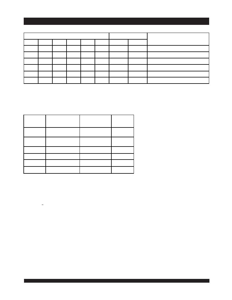
Truth Table II: Semaphore Read/Write Control (1)
Industrial Temperature Range
Inputs
Outputs
CE
H
X
H
X
L
L
R/ W
H
H
↑
↑
X
X
OE
L
L
X
X
X
X
UB
X
H
X
H
L
X
LB
X
H
X
H
X
L
SEM
L
L
L
L
L
L
I/O 8-15
DATA OUT
DATA OUT
DATA IN
DATA IN
____
____
I/O 0-7
DATA OUT
DATA OUT
DATA IN
DATA IN
____
____
Mode
Read Data in Semaphore Flag
Read Data in Semaphore Flag
Write D IN0 into Semaphore Flag
Write D IN0 into Semaphore Flag
Not Allowed
Not Allowed
5684 tbl 03
NOTE:
1. There are eight semaphore flags written to via I/O 0 and read from all of the I/O's (I/O 0 -I/O 15 ). These eight semaphores are addressed by A 0 -A 2 .
Absolute Maximum Ratings (1)
Symbol
V TERM
Rating
Supply Voltage on V DD
Industrial
-0.5 to +2.9
Unit
V
with Respect to GND
V TERM (2)
Terminal Voltage with
-0.5 to V DD +0.3
V
Respect to GND
T BIAS (3)
T STG
T JN
Temperature Under Bias
Storage Temperature
Junction Temperature
-55 to +125
-65 to +150
+150
o
o
o
C
C
C
I OUT
DC Output Current
20
mA
5684 tbl 04
NOTES:
1. Stresses greater than those listed under ABSOLUTE MAXIMUM RATINGS may cause permanent
damage to the device. This is a stress rating only and functional operation of the device at these
or any other conditions above those indicated in the operational sections of this specification is
not implied. Exposure to absolute maximum rating conditions for extended periods may affect
reliability.
2. V TERM must not exceed V DD + 0.3V for more than 25% of the cycle time or 10ns maximum, and
is limited to < 20mA for the period over V TERM = V DD + 0.3V .
3. Ambient Temperature under DC Bias. No AC Conditions. Chip Deselected.
6.42
发布紧急采购,3分钟左右您将得到回复。
相关PDF资料
IDT70P258L55BYI
IC SRAM 128KBIT 55NS 100BGA
IDT70T3339S200BCG
IC SRAM 9MBIT 200MHZ 256BGA
IDT70T3509MS133BP
IC SRAM 36MBIT 133MHZ 256BGA
IDT70T3519S133DRI
IC SRAM 9MBIT 133MHZ 208QFP
IDT70T3539MS166BCG
IC SRAM 18MBIT 166MHZ 256BGA
IDT70T3719MS166BBG
IC SRAM 18MBIT 166MHZ 324BGA
IDT70T633S10BCI
IC SRAM 9MBIT 10NS 256BGA
IDT70T651S12DRI
IC SRAM 9MBIT 12NS 208QFP
相关代理商/技术参数
IDT70P257L55BYGI8
功能描述:IC SRAM 128KBIT 55NS 100BGA RoHS:是 类别:集成电路 (IC) >> 存储器 系列:- 标准包装:45 系列:- 格式 - 存储器:RAM 存储器类型:SRAM - 双端口,异步 存储容量:128K(8K x 16) 速度:15ns 接口:并联 电源电压:3 V ~ 3.6 V 工作温度:0°C ~ 70°C 封装/外壳:100-LQFP 供应商设备封装:100-TQFP(14x14) 包装:托盘 其它名称:70V25S15PF
IDT70P257L55BYI
功能描述:IC SRAM 128KBIT 55NS 100BGA RoHS:否 类别:集成电路 (IC) >> 存储器 系列:- 标准包装:1,000 系列:- 格式 - 存储器:RAM 存储器类型:SRAM - 双端口,同步 存储容量:1.125M(32K x 36) 速度:5ns 接口:并联 电源电压:3.15 V ~ 3.45 V 工作温度:-40°C ~ 85°C 封装/外壳:256-LBGA 供应商设备封装:256-CABGA(17x17) 包装:带卷 (TR) 其它名称:70V3579S5BCI8
IDT70P257L55BYI8
功能描述:IC SRAM 128KBIT 55NS 100BGA RoHS:否 类别:集成电路 (IC) >> 存储器 系列:- 标准包装:45 系列:- 格式 - 存储器:RAM 存储器类型:SRAM - 双端口,异步 存储容量:128K(8K x 16) 速度:15ns 接口:并联 电源电压:3 V ~ 3.6 V 工作温度:0°C ~ 70°C 封装/外壳:100-LQFP 供应商设备封装:100-TQFP(14x14) 包装:托盘 其它名称:70V25S15PF
IDT70P258L55BYGI
功能描述:IC SRAM 128KBIT 55NS 100BGA RoHS:是 类别:集成电路 (IC) >> 存储器 系列:- 标准包装:1,000 系列:- 格式 - 存储器:RAM 存储器类型:SRAM - 双端口,同步 存储容量:1.125M(32K x 36) 速度:5ns 接口:并联 电源电压:3.15 V ~ 3.45 V 工作温度:-40°C ~ 85°C 封装/外壳:256-LBGA 供应商设备封装:256-CABGA(17x17) 包装:带卷 (TR) 其它名称:70V3579S5BCI8
IDT70P258L55BYGI8
功能描述:IC SRAM 128KBIT 55NS 100BGA RoHS:是 类别:集成电路 (IC) >> 存储器 系列:- 标准包装:45 系列:- 格式 - 存储器:RAM 存储器类型:SRAM - 双端口,异步 存储容量:128K(8K x 16) 速度:15ns 接口:并联 电源电压:3 V ~ 3.6 V 工作温度:0°C ~ 70°C 封装/外壳:100-LQFP 供应商设备封装:100-TQFP(14x14) 包装:托盘 其它名称:70V25S15PF
IDT70P258L55BYI
功能描述:IC SRAM 128KBIT 55NS 100BGA RoHS:否 类别:集成电路 (IC) >> 存储器 系列:- 标准包装:1,000 系列:- 格式 - 存储器:RAM 存储器类型:SRAM - 双端口,同步 存储容量:1.125M(32K x 36) 速度:5ns 接口:并联 电源电压:3.15 V ~ 3.45 V 工作温度:-40°C ~ 85°C 封装/外壳:256-LBGA 供应商设备封装:256-CABGA(17x17) 包装:带卷 (TR) 其它名称:70V3579S5BCI8
IDT70P258L55BYI8
功能描述:IC SRAM 128KBIT 55NS 100BGA RoHS:否 类别:集成电路 (IC) >> 存储器 系列:- 标准包装:45 系列:- 格式 - 存储器:RAM 存储器类型:SRAM - 双端口,异步 存储容量:128K(8K x 16) 速度:15ns 接口:并联 电源电压:3 V ~ 3.6 V 工作温度:0°C ~ 70°C 封装/外壳:100-LQFP 供应商设备封装:100-TQFP(14x14) 包装:托盘 其它名称:70V25S15PF
IDT70P259L65BYGI
制造商:Integrated Device Technology Inc 功能描述:IC SRAM 128KBIT 65NS 100FPBGA
